Morgan Moments – Inside the E H Werner Power Plant
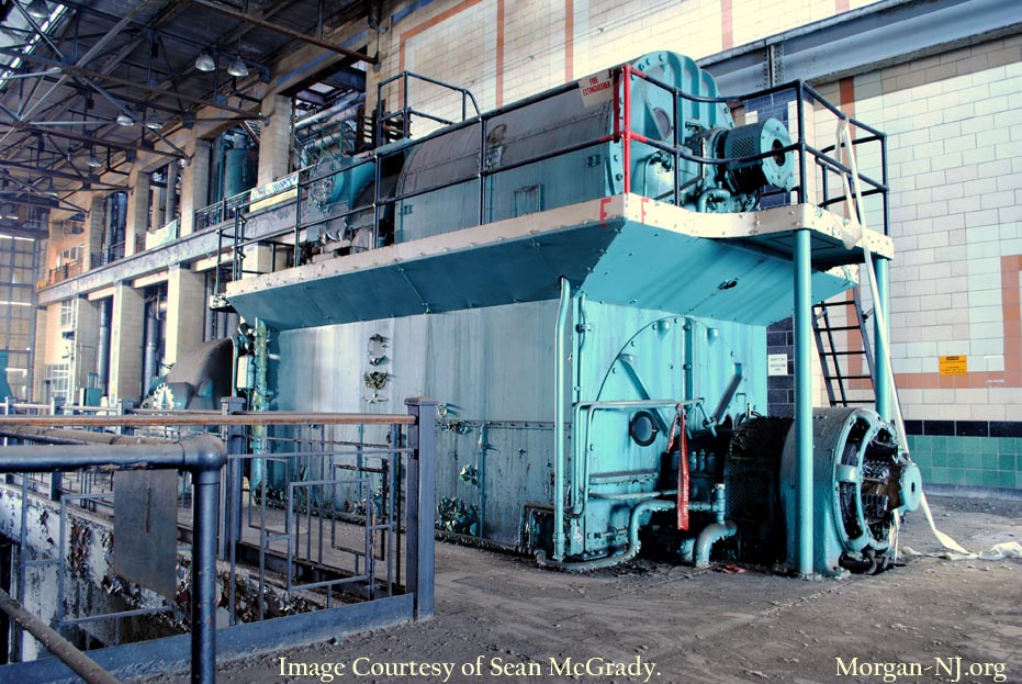
Interior View of the E. H. Werner Building Showing JCP&L’s 1930 Vertical Compound Turbine-Generator Unit #1. Photo Courtesy of Sean McGrady.
The majority of the content of this page has only been made possible primarily because of the generous efforts of two people. A huge thank you goes to my college friend Valerie for finding a copy of the July 15, 1930 issue of Power Plant Engineering which featured an article about South Amboy’s then brand spanking “New Plant on Raritan Bay at South Amboy, N. J.” Another huge thank you goes to Morgan-NJ.org reader Sean McGrady for his spectacular photos of the inside of that same soon-to-be leveled E H Werner Power Plant. Jason saw the write-up about the history of the building and contacted me to offer the usage of his photos. Yet another thank you goes to Holly Hughes Horning of the Historical Society of South Amboy for providing the exterior photo of the Intake Channel.
As well as I can and as non-technical as I can, I’ll try to explain how this power plant operated in its early days primarily via translation of the content of the Power Plant Magazine article. This article is even too technical for me so I can’t guarantee that this explanation will in all cases be done well enough. We’ll try anyway.
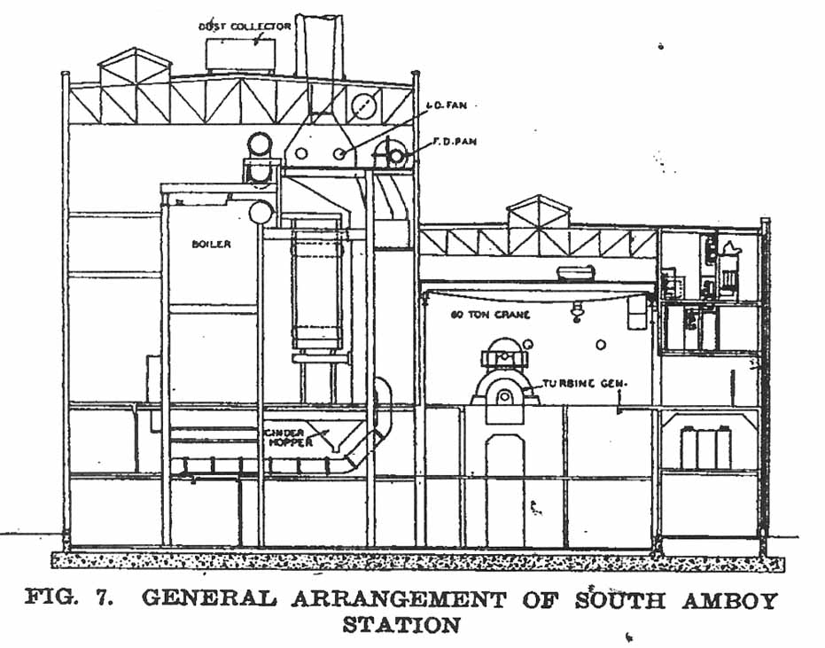
Cut Away Side View of the E. H. Werner Building Looking West. Image Courtesy of the July 15, 1930 Issue of Power Plant Engineering Magazine.
On the big picture, the plant did what power plants the world over still do, that is, heat water to make steam to turn turbines which turn generators to make electricity; conceptually very simple. When it opened in 1930, this power plant used coal to heat water, obtained from deep wells and stored in underground storage tanks, to produce steam at a pressure of 1400 pounds per square inch at 750 degrees Fahrenheit. After the steam spun the turbines, it was cooled back to liquid form using water from Raritan Bay which was then returned to Raritan Bay. The evaporated water then flowed back into the two 10,000 gallon underground water tanks outside the station.
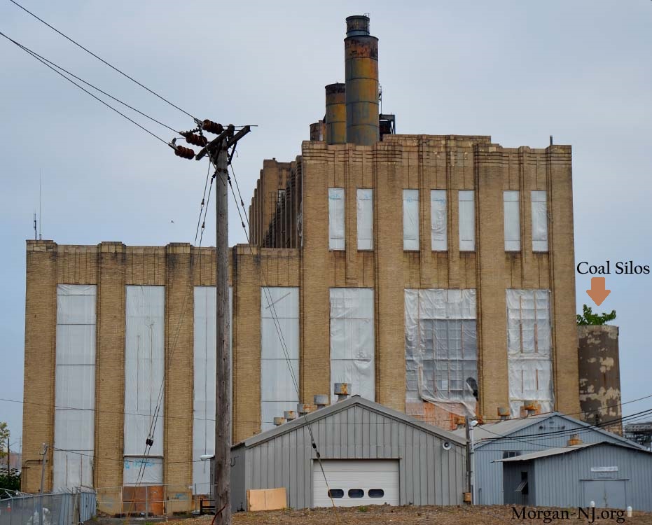
It all started with coal. Delivered either via barges from Raritan Bay or via hopper bottom railroad cars, the coal would be brought to the “coal breaker” which appears to have been located in the tower next to the coal dock (see this tower here). In the coal breaker, coal was crushed and either sent down a chute to the storage area for later retrieval by the “drag scraper” or moved by an elevated and enclosed conveyer belt into six 125 ton reinforced concrete silos located on the south side of the south wall.
The area on the south side of the building, between the bay and what is now the four exterior diesel powered generators, used to be where the coal was stored. There was space for 25,000 tons of coal.
Inside the building, there were (and still are – so far) three boilers each with its own set of five “air-swept ball type” of coal pulverizing mills – one pulverizing mill for each burner in each boiler. Each pulverizing mill had a 5000 pound per hour capacity. 15 mills times 5000 pounds per hour equals 75,000 pounds per hour or 37.5 tons per hour. In 24 hours that would be 900 tons of coal (1,800,000 pounds) – that’s a lot of coal per day! Wonder if they ever hit that number?
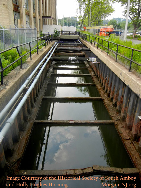
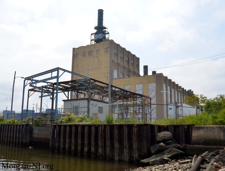
View of the Input Channel of the E. H. Werner Building. Image Courtesy of The Historical Society of South Amboy and Holly Hughes Horning.
As previously mentioned, the water for the steam would come from wells and storage tanks, and the water for the condensing equipment would come from Raritan Bay via the Input Channel on the north side of the building.

Cut Away Basement Floor Plan for the Original E. H. Werner Building Looking West. Image Courtesy of the July 15, 1930 Issue of Power Plant Engineering Magazine.
Per Power Plant Engineering:
Sea water from Raritan Bay forms the cooling medium for the condensers. This water flows from the harbor to the plant through an open channel lined on the sides with interlocking sheet steel piling. After passing through the condensers, the circulating water flows back to the harbor through a similar channel and a precast concrete discharge tunnel on the other side of the power plant building, discharging into the harbor 200 ft. away from the intake channel. The intake canal and discharge canal are separated from each other by a stone breakwater.
The channels are 17 ft. 5 in. wide and at low tide allows 15 ft. of water necessary for the ultimate capacity of the station. The unusual trash racks are provided where the intake tunnels enter the building and a head of each condenser are two 45,000-g.p.m. [gallons per minute] traveling screens, provision being made in screen capacity for the third unit.
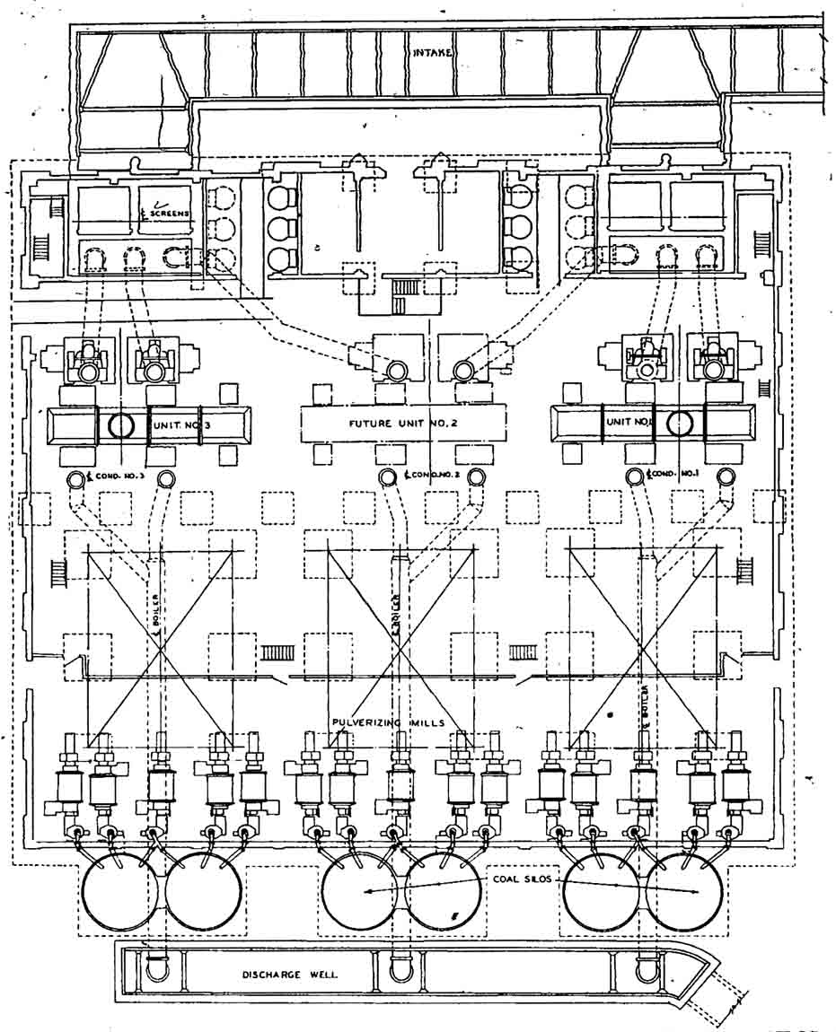
Basement Floor Plan for the Original E. H. Werner Building (North Up). Image Courtesy of the July 15, 1930 Issue of Power Plant Engineering Magazine.
Two motor-driven condenser circulating pumps, each of 21,000 g.p.m. capacity, are provided to force the water through each condenser. The intake channel runs along close beside the building with bays at each end opposite the present generating units, Nos. 1 and 3, leading in to the traveling screen wells just inside the building wall… Condenser circulating water discharges from the condensers through 48-in. pipe leading under the boiler house to the discharge channel…
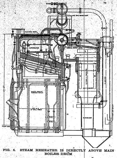
Cut Away View of the Babcock & Wilcox Co. Boiler for the Original E. H. Werner Building. Image Courtesy of the July 15, 1930 Issue of Power Plant Engineering Magazine.
The burners would of course heat the boilers to convert the water into steam. The three original 1930 boilers were pretty complex devices, more complex than will be elaborated on here. Flue gas was discharged out through the three stacks present on the roof of the building. It is interesting to note that the cylindrical exterior shape of the stacks on the roof are actually ornamental and mask the true shape of the discharge channel. Per Power Plant Engineering:
Each stack is of the steel venture type, with the induced draft fans and gas passages designed as integral parts of the stack. It is 4 ft. 10 in. in diameter at the throat, 10 ft. in diameter at the top and 60 ft. high above the top of the boiler supporting steel on which it rests. A cylindrical casing was placed around each stack to give it the appearance of a straight steel stack but this has nothing to do with its operation. It was done solely because it was felt that the original shape of the stack did not accord with the design of the building itself.
The internal shape of the stacks can be seen above in Figure 7 from Power Plant Engineering.
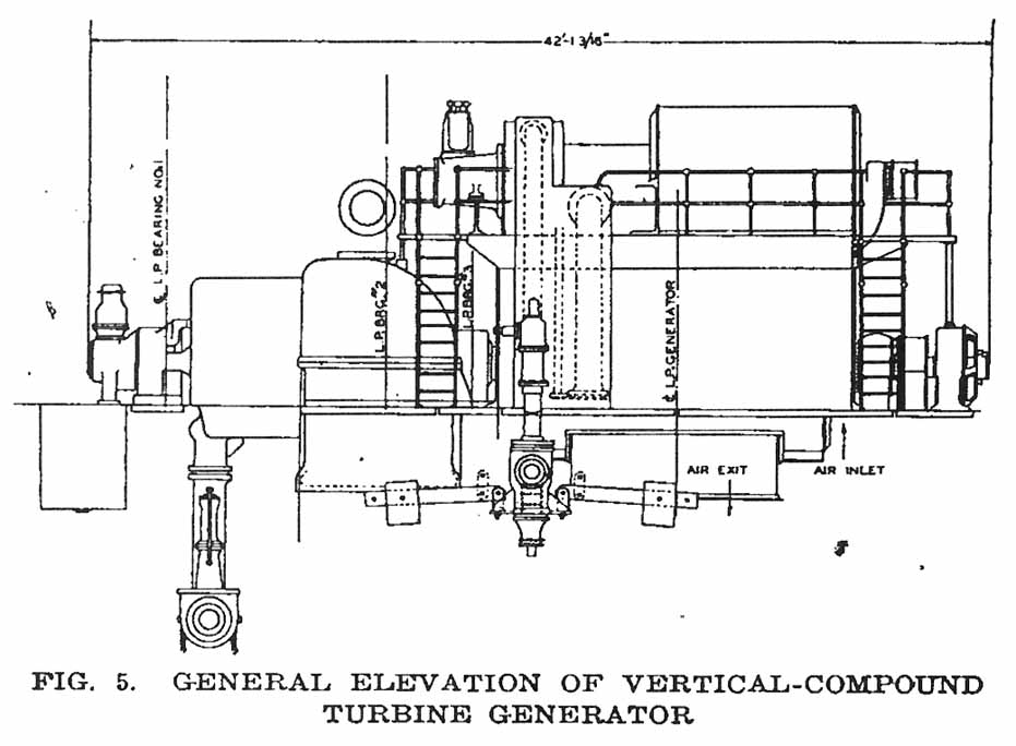
Cut Away View of the General Electric Co. Vertical Compound Turbine-Generator for the Original E. H. Werner Building. Image Courtesy of the July 15, 1930 Issue of Power Plant Engineering Magazine.
The high pressure steam from the boilers was piped to the turbine blades of the two General Electric 25,000 kilowatt vertical compound turbo-generators (seen in the top photo of this page). Note that South Amboy had the very first installation of this new type of turbine-generator. After this, the steam was condensed back to water as previously mentioned.
There were three different voltages produced at this plant: 33 kilovolt, 66 kilovolt and 132 kilovolt. Power was transmitted via the power lines along the right of way still used today which cut over what was once the Stevensdale Estate.
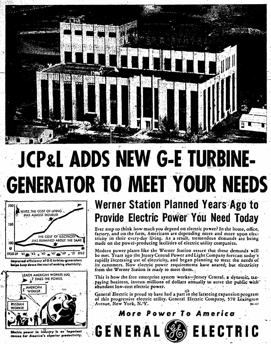
In the 1950s, the plant was expanded to add one additional and more powerful General Electric generator.
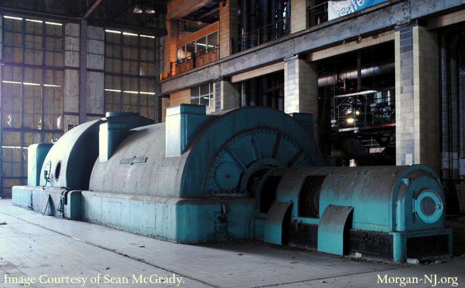
Interior View of the E. H. Werner Building Showing JCP&L’s 1953 General Electric Turbine Generator. Photo Courtesy of Sean McGrady.
As was touched on in the other Morgan-NJ.org page about this power plant, when one looks closely at this power station, it is actually quite a remarkable piece of architecture. Per Power Plant Magazine:
STATION IS EXAMPLE OF GOOD ARCHITECTURE
Both interior and exterior of the South Amboy station present a most pleasing appearance. As shown in the headpiece, the building design is simple; it is dependent on two principal masses, with good fenestration. The vertical lines of the pilasters, the conservative decoration at the top of each pilaster and the continuous horizontal lines of the stone trim at the top all contribute their parts to the total satisfactory effect.
The station is of light buff face brick and steel construction. As is evident, the wall space between pilasters is practically all window, providing splendid lighting and ventilation. This is especially noticeable in the boiler room, where the absence of overhead bunkers permits full advantage to the taken of the windows and the monitor over the firing aisle.
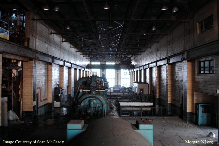
Interior View of the E. H. Werner Building Turbine Room Looking West Toward the Two 1930 Vertical Compound Turbine-Generators. Note the Glazed Tiled Walls. Photo Courtesy of Sean McGrady.
The interior of the boiler room is left in the original light colored brick of the building walls. In the turbine room, however, an unusually pleasing appearance is obtained by use of glazed tiled walls and panels outlined by rows of dark brown tile. The turbine room floor is of brown tile.
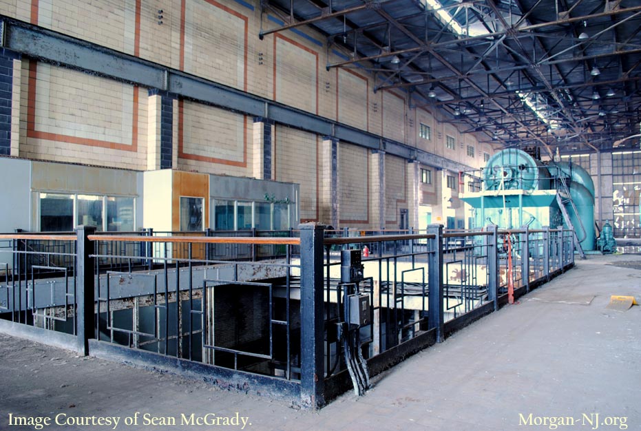
Interior View of the E. H. Werner Building Turbine Room Looking East Toward Turbine #1 From Near Turbine #3. Photo Courtesy of Sean McGrady.
It is evident from the foregoing description that South Amboy plant differs in many of its details from other power plants. Simplicity of operation and high economy with low first cost were the fundamental requirements that determined many of these details.
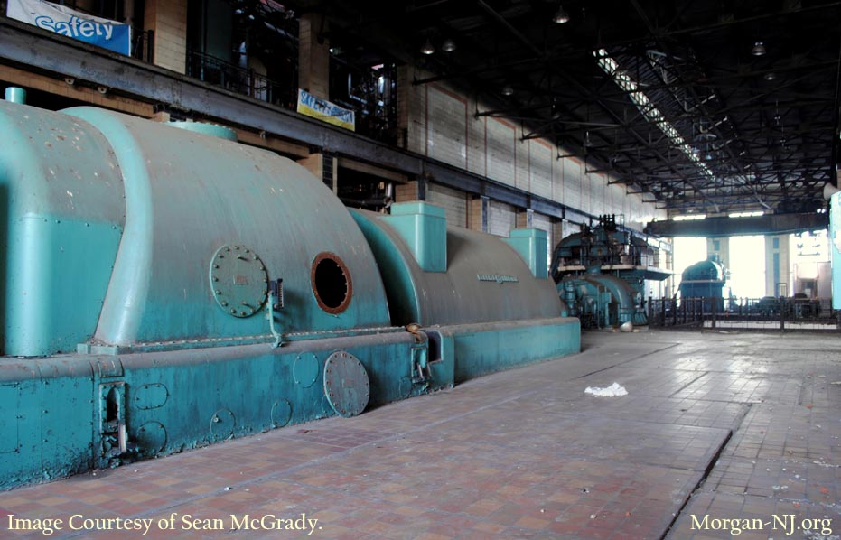
Interior View of the E. H. Werner Building Turbine Room Looking West. Note the 1953 General Electric Turbine in the Foreground and the Two 1930 General Electric Turbines and Overhead Crane in the Background. Photo Courtesy of Sean McGrady.
A point of particular interest in the design of the South Amboy station was the close cooperation and interchange of ideas existing between the architects, manufacturers and engineers in the design of this station. The result is an outstanding example of what can be done by utilizing the ability and initiative of those involved.
The South Amboy station was designed and constructed by the Electric Management and Engineering Corp. of New York City for the Jersey Central Power and Light o., and operating subsidiary of the National Electric Power Co.
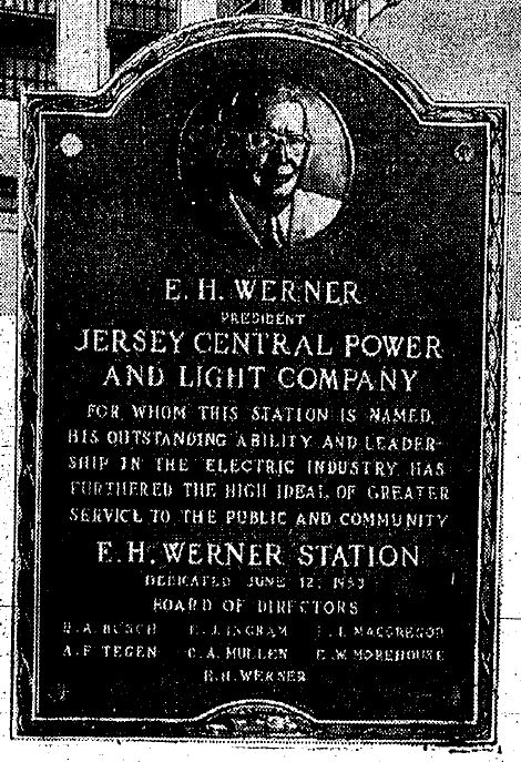
As of the time of this writing, the removal of asbestos from the interior is likely still in progress. The exact date of the implosion isn’t too well known, at least it isn’t known here. I have heard that the Historical Society of South Amboy will be receiving the 1953 dedication plaque pictured above so that it will not be lost forever.
I started my career at Werner station
in 1964 as a utility worker fresh out of
the Navy. I have many good memories
which I list below.
— At real low tides we would still retrieve
land mines from the mud of the river.
We would store them until we had about
A dozen. Then the boss would call the
Army to dispose of them.
— I received my Firemans license and
Stationary engineers license there
and ran the boilers and turbines.
— I left there in 1967 to go to Sayreville
station in maintenance. I came back
to Werner in 1976 to overhaul the
Gas turbines. Nothing changed in
those past years. It was like coming
home.
— In 1978 I went to Oyster Creek for
the rest of my career
I too started as a “Cadet Engineer” at E. H. Werner in July of 1975. I worked on maintaining the CTs with other maintenance engineers; Vince Foglia, John Tokar and others. It was an interesting time to see and work on the new W501s alongside the old units. I then left to work at Oyster Creek and eventually with the DOE out her at Hanford WA.
do u have any info on the sayreville generating station? if so can i hear.
As Tom Brownridge did, so many of us started our careers with JCP&L as entry level workers. The company offered opportunity for those willing to take advantage. The possibilities back then seemed limitless. Training was available in house on the job. Off-site academic or trade schooling would be reimbursed. One could choose a career path such as, plant operator, electrician, mechanic or lineman and advance to supervisor, manager and all the way up to president (Google, James R. Leva).
Times have changed and corporate America has lost its vision on training and developing its greatest resource.
I started with JCP&L in 1978 and spent 21 years in Werner and Sayreville Stations and was severed when GPU reorganized and was sold off a piece at a time. I’m sorry to see the old sites die but will always grateful for what I took from my experiences.
Amazing! I worked for JCP&L from 1986 on at the Gilbert facility in Holland Township. As times changed and workforces were pared down the employees of Gilbert , Sayreville and Werner all banded together for operational and repair duites. That being said I had the chance while on a standby assignment at Werner to go into the building after it was abandoned. I had even taken pictures however they were lost. I thank you for saving these images and the history of the station. Too many the modern day impressions of buildings like this are that they are eyesores. When looking deeper into it you actually see the hearts and souls of those who designed it to be…practical and beautiful. Also it should be mentioned that the building serves as a sort of freeze frame in time should one take the time to look…names scratched in paint… discarded personal items and drawings. Ive worked sites like these and I have been fortunate enough to have free exploring acces to see everything and at times visit with a few ghosts. Losing these sites while the normal march of time and or commerece is inevatible my heart saddens to see them go. Thanks to all those great folks that worked there over the years ….you all did a great job!
David J Lucas
You did have to get close to it to appreciate its beauty. As I understand it, it is being demolished right now.
Are you going to follow up with photos of the dismantled station? Tom
Hi Tom,
Yes, someday. I don’t live anywhere near by. Some friends have provided some intermediate photos of the demo but I have not included them yet.
Really nice document! Thank you!
Thanks!
Thanks so much for the excellent writeup on the Werner Power Plant. I was always interested on how it looked on the inside.
I was wondering where I could find the actual article in Power Plant Engineering? I’m trying to use my college library’s database to locate the article.
Hi Daniel. Glad you liked it! It can be found on microfilm in New York City (Manhattan) at the Science, Industry, and Business Library. 188 Madison at 34th St. (917) 275-6975. The plant was finally torn down. What a bummer! Let me know if you have problems getting a copy or live so far away as to make it impractical. Verne
Thanks so much for the quick reply! I was able to acquire an electronic-version copy through my college library. It’s a bummer the plant was torn down and rather a strange sight as I saw it, from the NJ Transit train a few weeks ago.
What a great piece about a beautiful building. Do you know whether Sean McGrady has other photos of the interior? I’d love to see them.
I think I posted all of the ones he sent. The building is now just a memory!
Heather i believe i have a few more. If you give me a way to contact you, i can send you some.
Digging in some long ago memory –
The summer I turned 18, I landed a job with the JCP&L as a cadet engineer. My assignment was at the E.H. Werner station. The position was created by the company to expose college students with aspirations of becoming power engineers to the day to day operations of a power plant. As a first year cadet, you spent time with the different operational positions in the plant, and got to see how things were run and done. You couldn’t replace the union hands, but could do anything as long as one of the qualified people was with you. They made use of that, going for coffee while you did the job. All OK, one could at least do something rather than sit or stand around watching. Or they might give you the keys to the dump truck and send you out for the coffee instead.
One thing they would let you do without an operator with you was clean the trash rack washout pits. The pits were around 8 feet deep, maybe 4X4 feet and a grating bottom above the cooling water intake channels. The trash racks backwashed automatically, flushing fish, seaweed, shells, rocks and other stuff that might clog the condenser tubes into these pits. The water returned to the canal, and the “stuff” stayed in the pits until someone went down and shoveled it out.
The back story on those pits is that Raritan Bay was home to a lot of scavenger type critters, including horseshoe crabs. It was very common to find lots of them there. One morning, Charlie (another cadet) and I got the call to shovel the pits. We got the tractor, set the bucket down at the edge as a place to put the mess, lifted the cover and were met with a nearly full pit of crabs, most still alive. It was my turn to go in –. The accepted method of getting the crabs out was to pick them up by the tail and heave them up to the bucket. Some of them didn’t make it and came back down. One more reason for hard hats, raining horseshoe crabs.
can you do one of these on the sayreville jcp&l generating station please?
Glad you enjoyed the piece about the Werner Plant. If I ever do one about the Sayreville one, it likely won’t be for a very long time. Perhaps the Sayreville Historical Society might have some coverage of it in their museum. Their museum in Lower Sayreville is an interesting place to visit.
thank you for responding to me! I have been to the museum, I am a resident of Sayreville. I asked you about the sayreville plant because I thought since you knew so much werner (by the way well done) you might know something about its sister power plant (the Sayreville plant) i’m glad you’re doing a report on the sayreville plant because i’m writing a book on the plant so i”m so excited to hear what info you can find that I don’t already know. I know for a fact that information for the plant is very scarce, but don’t let that deter you. just do a lot of research dig deep matter of fact I stumbled upon this by researching for my book so yeah thanks for responding!
Hey Brody, did you ever find more information on the Sayreville Station? It seems like they’re dismantling the plant now.
Yes, I’m mad late to this but, I’ve spoke to someone who works there he said the whole thing was supposed to come down by the end of 2020-21 but here we are in 2022 and no more demolition has happened on it so I’m guessing something is stopping them from demolishing the plant, or they changed there mind. Really wish they didn’t get rid of the coal conveyor belts and the thing that hung over the water. Since I made my first post here I’ve gained a lot of info about the plant construction began in 1928 opened officially in 1930, had two major additions added to it in the 40s and 50s. Closed in 1970 and was passed off to a new owner (I think reliant energy). Also I now have tons of pictures of the inside of it.
This is an amazing writeup. I would love to somehow get a copy of the issue of power plant engineering magazine that this plant was featured in. Would this be possible?
Glad you enjoyed the write up! The July 1930 issue of Power Plant Engineering is available on microfilm (microfiche?) at the New York Public Library. Not sure how you would be able to get a copy unless they provide a service to print it for you.
This site will now be used by Rise Light & Power for a power grid distribution site for New Jersey’s offshore wind farm. That seems right!